Limelight Sensor Line
A full-stack family of compact robotics sensors — PCB design, firmware, injection-moldable enclosures, and a pogo-pin programming jig for production.
Project Overview
The Limelight Sensor Line is a family of compact, purpose-built sensors designed for robotics applications. Each sensor shares a common form factor and connector interface, making them easy to integrate into robot designs.
Role: Full-Stack Product Developer — electronics, firmware, mechanical enclosures, and production tooling
Company: Limelight
Tools: KiCad, Embedded C, Onshape
Color Sensor
The color sensor uses the APDS-9999 for RGB color detection with I2C communication. Built around an MSP microcontroller for signal processing and PWM output.
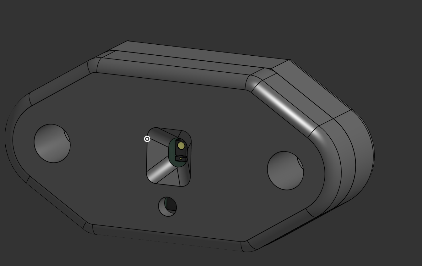
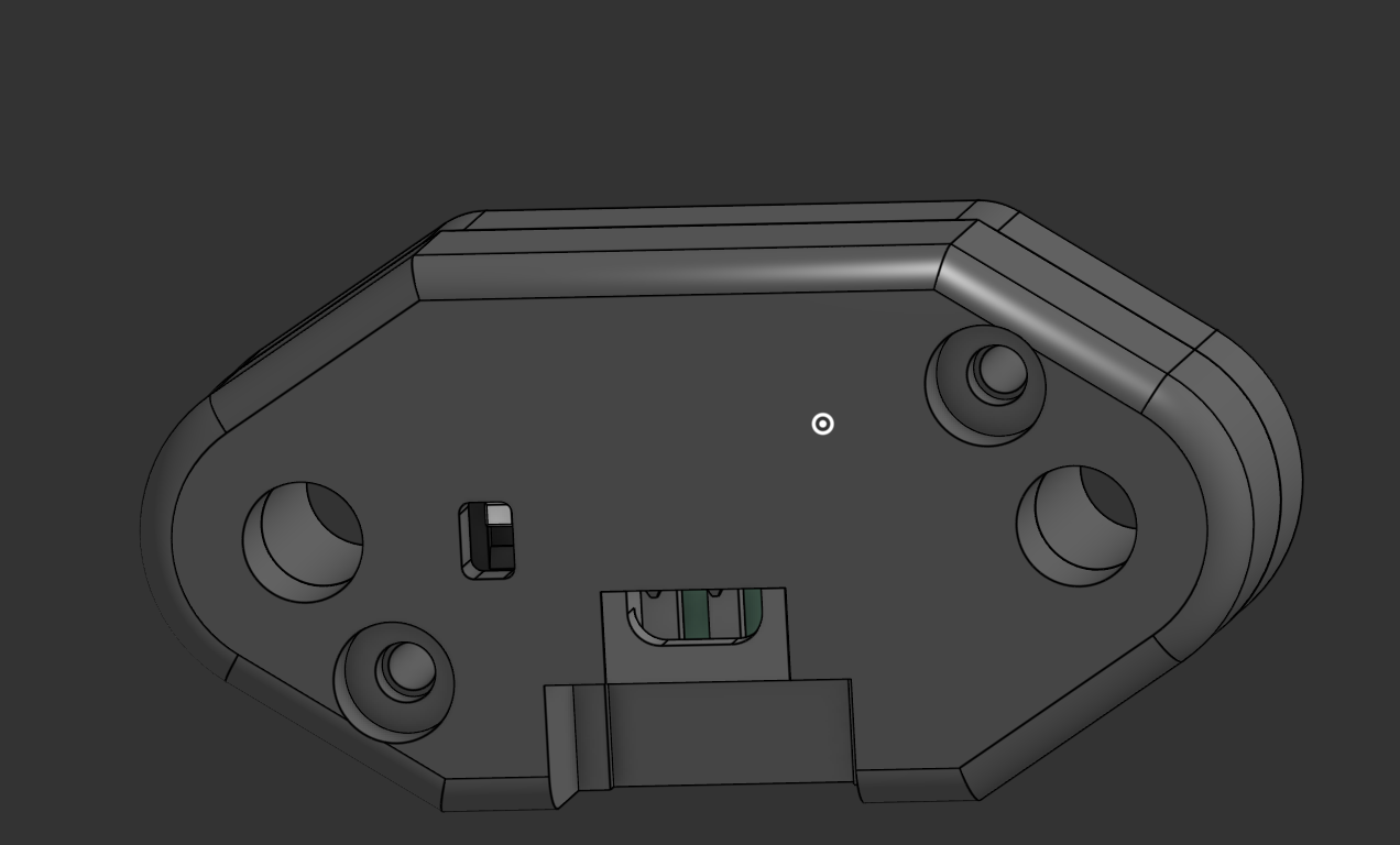
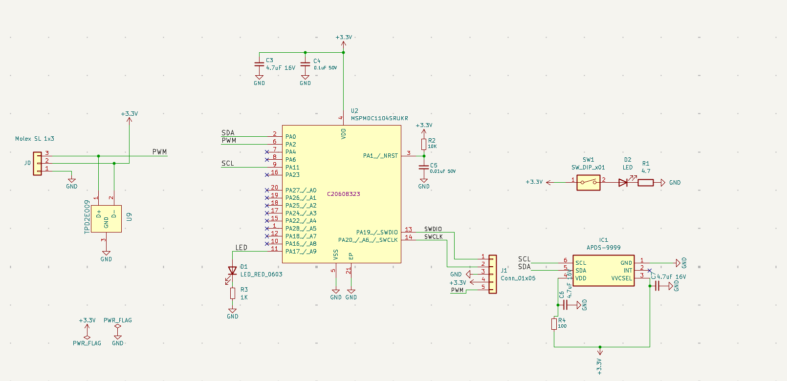
Key Components:
- MCU: MSP (C2060B323)
- Sensor: APDS-9999 RGB/Proximity sensor
- Interface: I2C (SDA/SCL), PWM output
- Connector: Molex SL 1x3
- Protection: TPD2E009 ESD protection
Distance Sensor
The distance sensor uses the VL53L4CD Time-of-Flight sensor with an RP2350A microcontroller for USB connectivity and advanced processing.
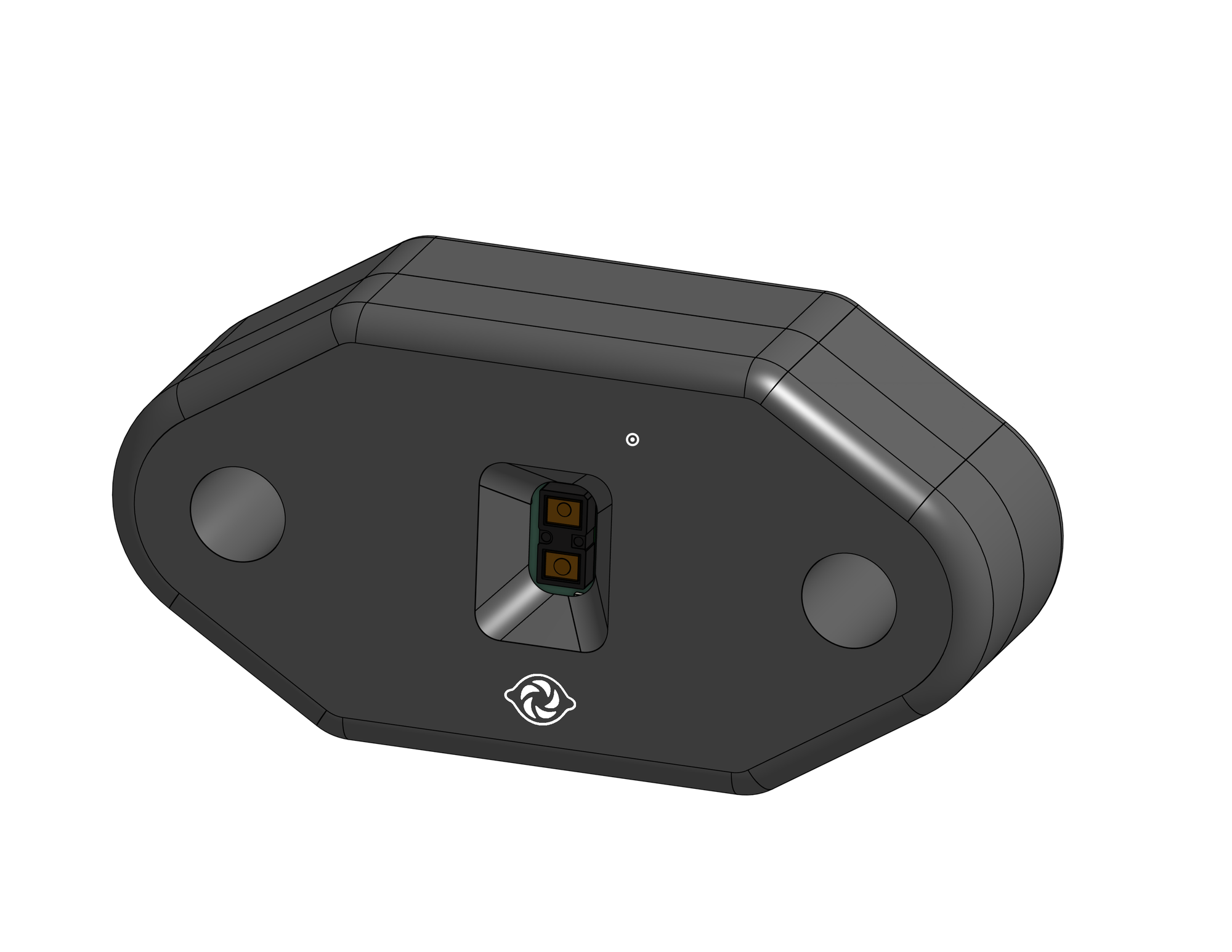
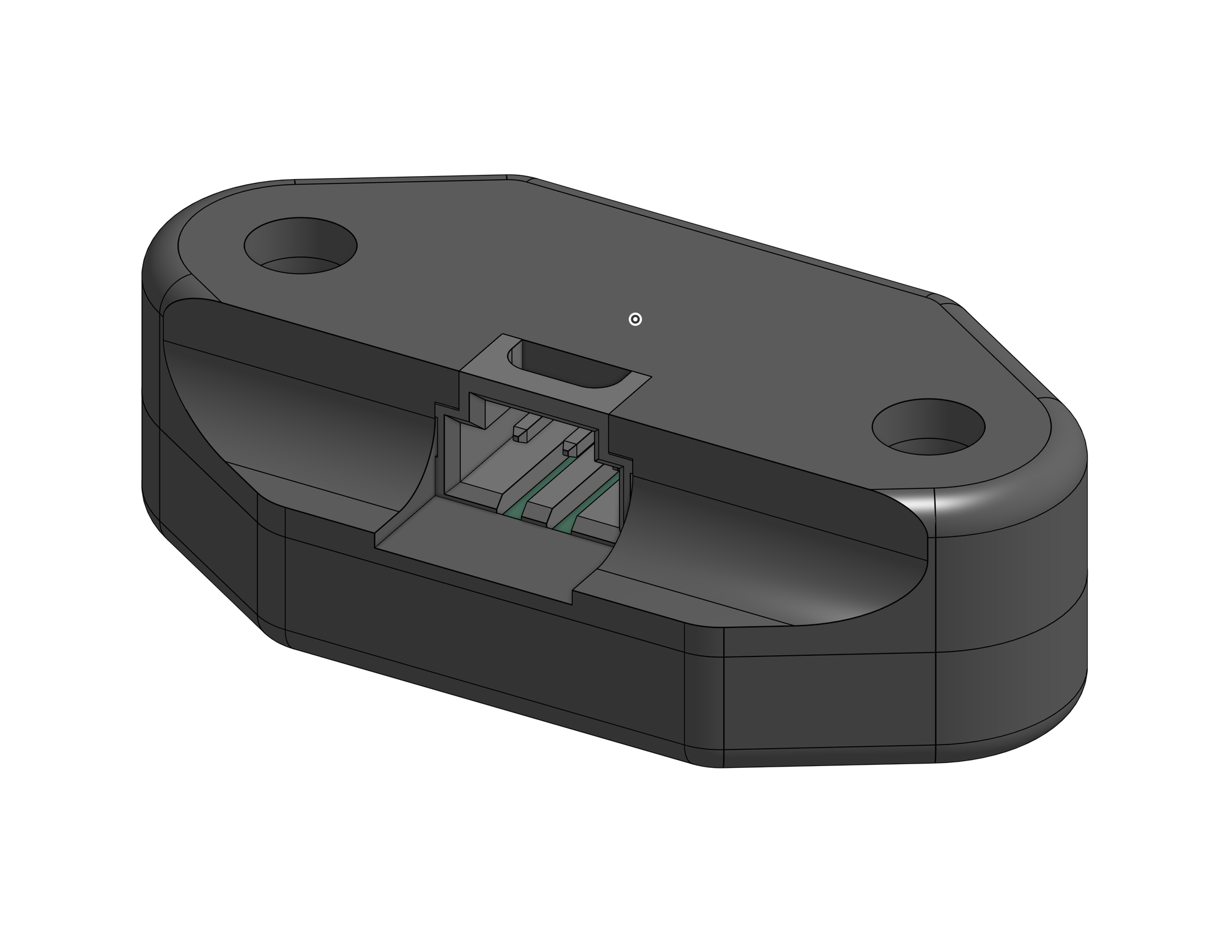
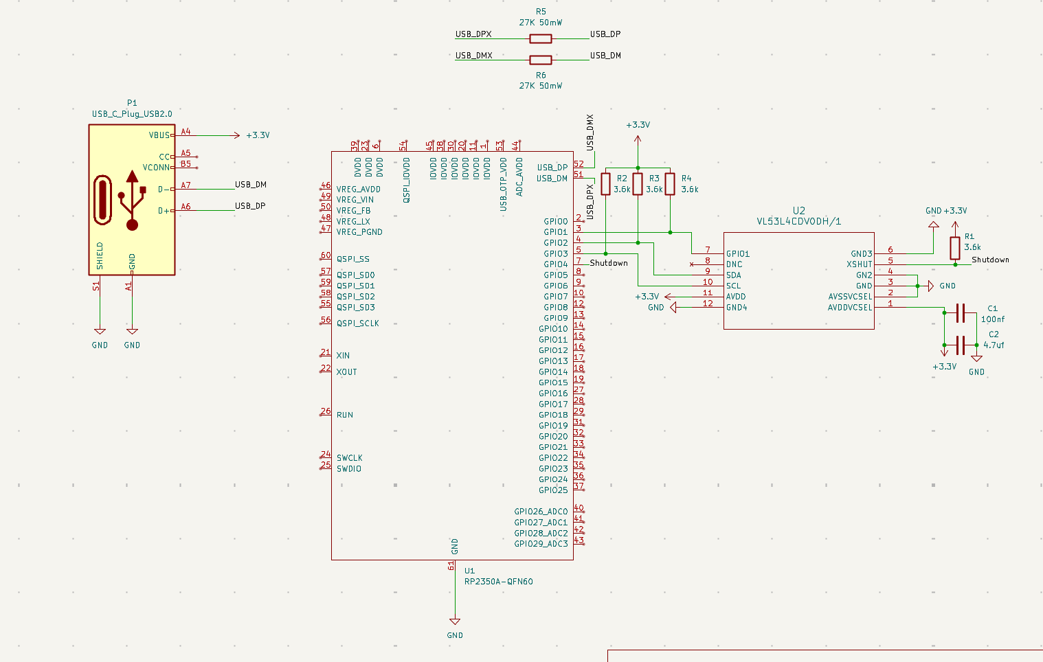
Key Components:
- MCU: RP2350A (QFN60)
- Sensor: VL53L4CDVODH/1 ToF distance sensor
- Interface: USB-C, I2C
- Features: QSPI flash support, USB 2.0
Hall Effect Sensor
The hall effect sensor uses the DRV5053 for magnetic field detection, sharing the same MSP microcontroller platform as the color sensor.
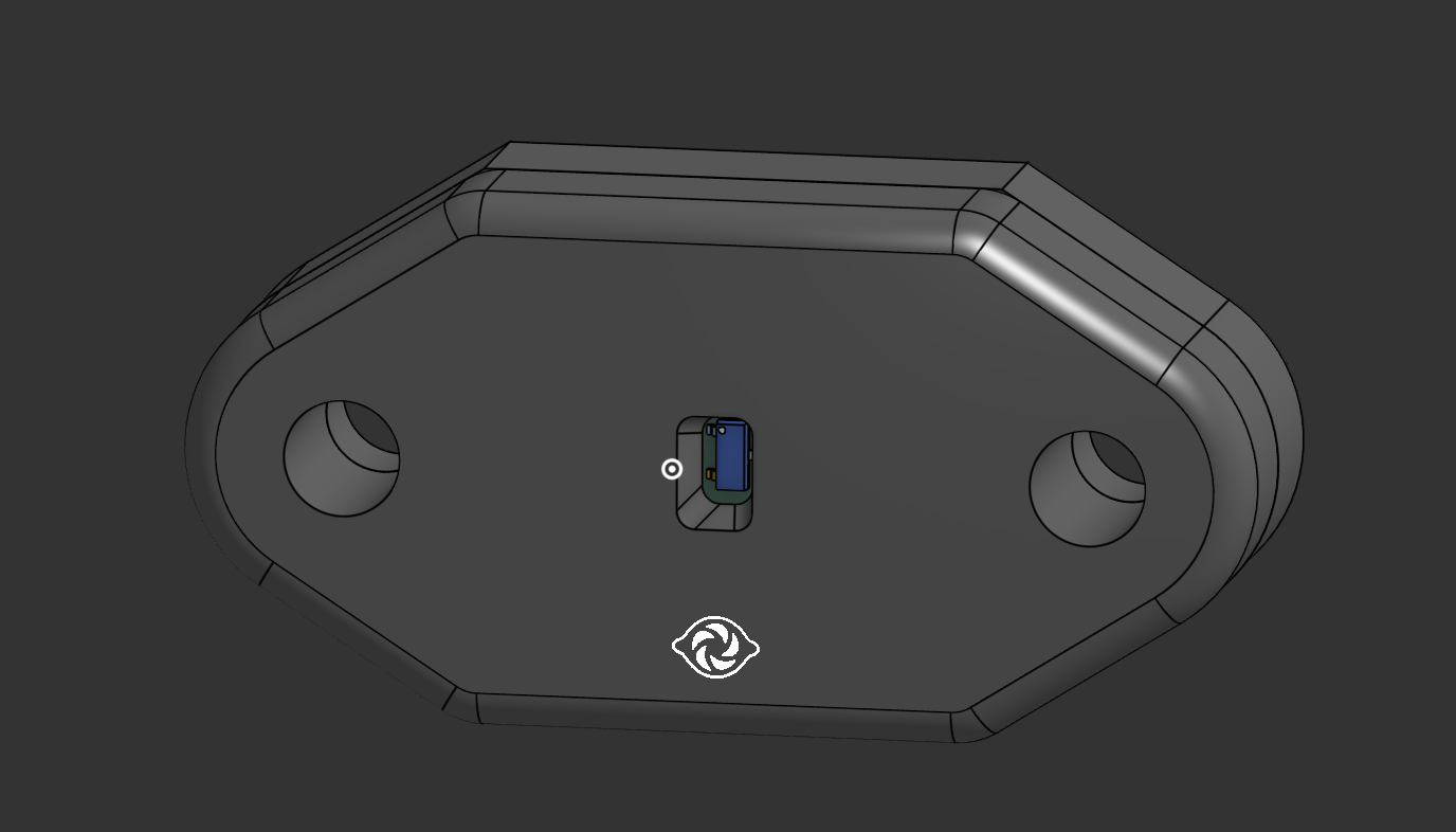
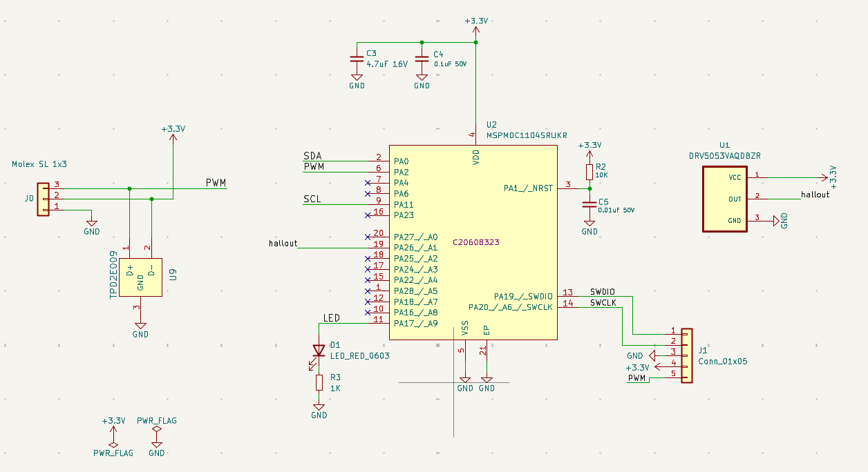
Key Components:
- MCU: MSP (C2060B323)
- Sensor: DRV5053VAQDBZR hall effect sensor
- Interface: PWM output
- Connector: Molex SL 1x3
- Protection: TPD2E009 ESD protection
Injection-Moldable Case Design
Every sensor in the line shares an enclosure designed from the start for injection molding, not just 3D printing. That meant designing each case around the realities of the mold: a clean parting line, consistent draft on every face, and no undercuts that would trap the part in the tooling.
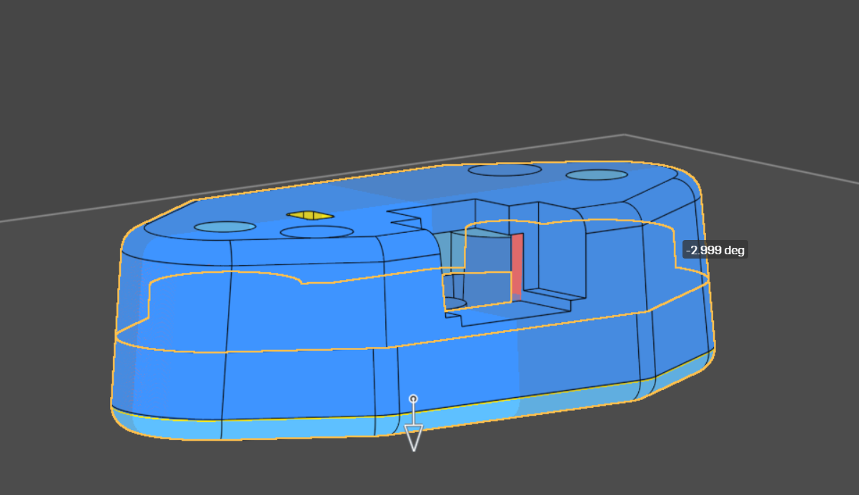
The render above is an Onshape draft analysis run against the pull direction (the arrow at the bottom of the part). Faces are shaded by their angle relative to the mold's opening direction — blue faces have positive draft and release cleanly, while any red face flags a wall that would lock against the tool. The geometry was tuned so the split respects the mold, holding draft angles down to ~3° while keeping the form factor compact.
Design-for-manufacturing considerations:
- Parting line: placed to split the case cleanly into two mold halves
- Draft analysis: every external and internal face checked against the pull direction
- No undercuts: features reworked so the part ejects without side actions
- Consistent wall thickness: for even cooling and to avoid sink marks
Pogo Programmer
To take the sensors from bench prototype to production, I designed a dedicated pogo-pin programming jig — a board that flashes firmware over SWD without soldering a single wire, plus a 3D-printed fixture that aligns each sensor PCB to the pins.
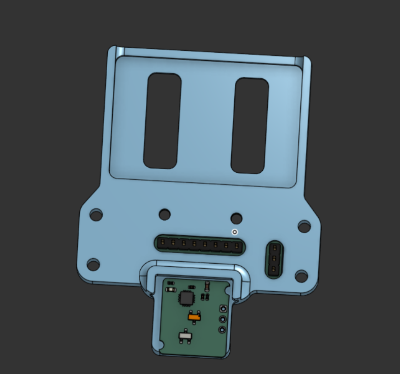
The 3D-printed cradle drops the sensor board onto the pogo pins at a repeatable position, so a board can be programmed and tested in seconds during a production run. Designing the board, the firmware, the case, and the tooling to manufacture and program it is what makes this full-stack product development — every layer from silicon to factory fixture is part of the same project.
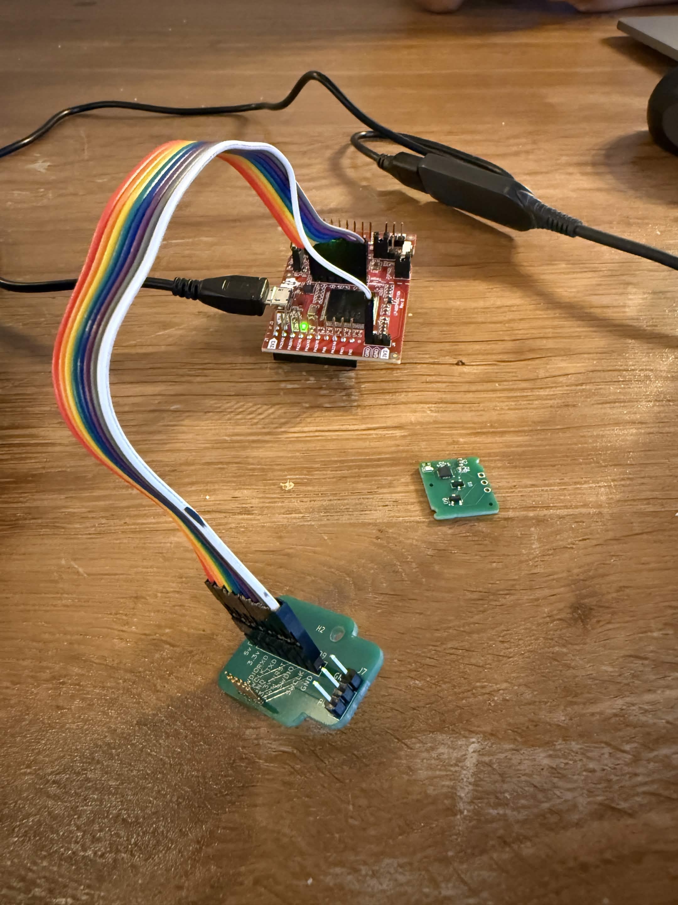
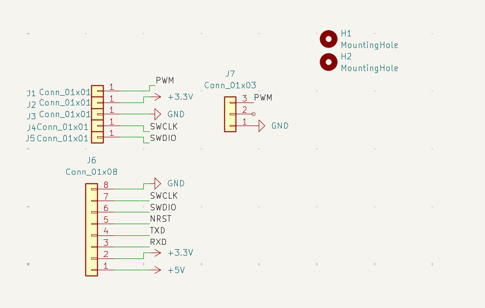
Programming Interface (J6):
- +5V, +3.3V power
- RXD, TXD serial
- NRST reset
- SWDIO, SWCLK debug
Tech Stack
| Area | Tools |
|---|---|
| PCB Design | KiCad |
| Firmware | Embedded C |
| MCU | MSP, RP2350A |
| Enclosure / DFM | Onshape (draft analysis, injection molding) |
| Production Tooling | 3D-printed pogo-pin programming jig |