Part of KUdos Custom Electronics Stack
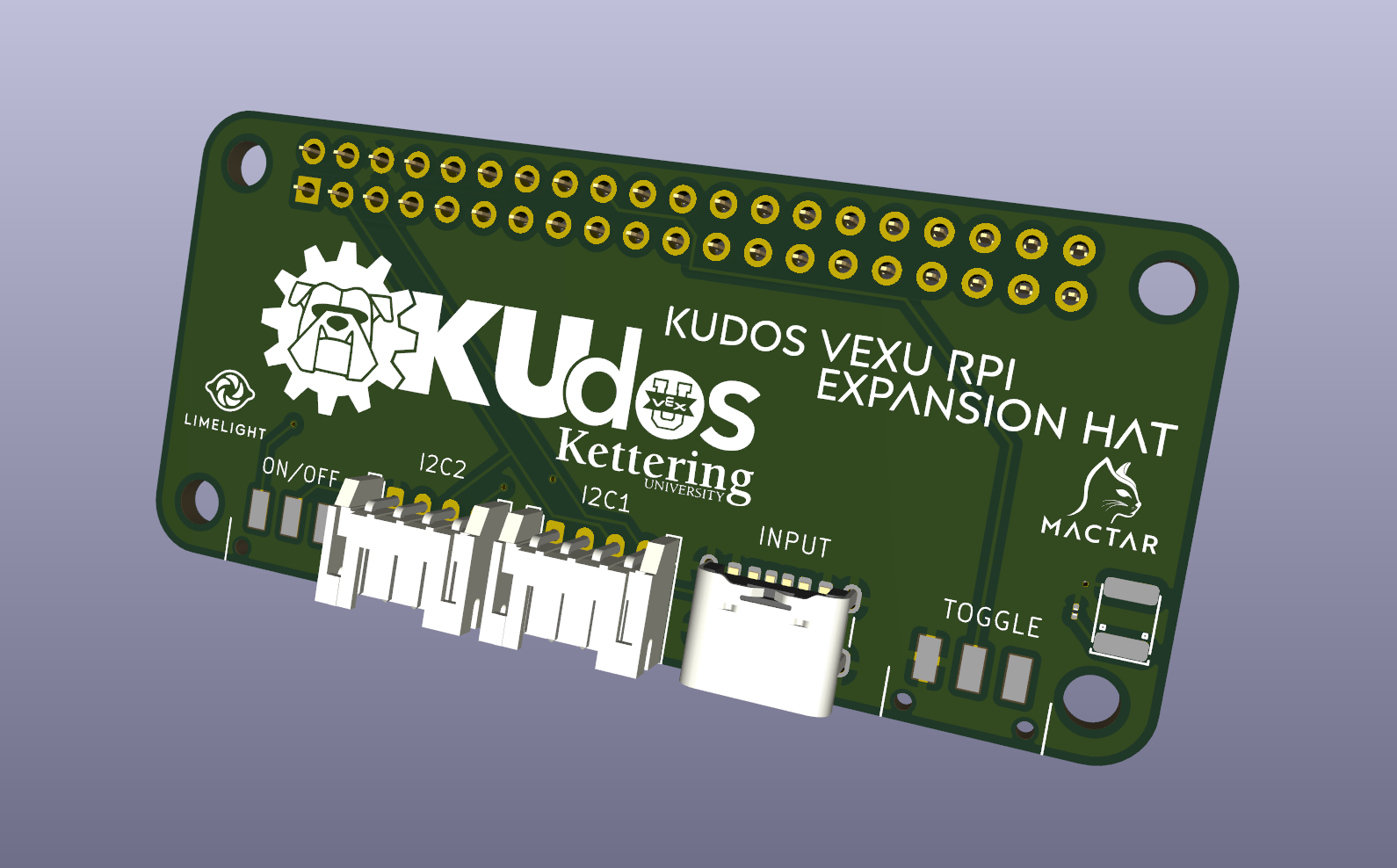
KUdos RPi Expansion HAT
A custom PCB for Raspberry Pi Zero 2W providing I2C interfacing and native RS485 communication for VEX-U robotics.
Project Overview
The KUdos RPi Expansion HAT is a custom PCB I designed to interface a Raspberry Pi Zero 2W with the KUdos VEX-U robot electronics stack. The board provides two I2C ports, native RS485 communication, Limelight camera integration, and power management for the coprocessor system.
This HAT is part of a fully custom electronics stack that the KUdos team developed for VEX-U competition, which is rare in the VEX ecosystem where most teams use stock electronics.
Role: PCB designer, including schematic capture, layout, and fabrication coordination.
Tools: KiCad, JLCPCB
Features
- Dual I2C Ports: Two independent I2C buses for sensor integration
- RS485 Interface: Native RS485 for communication with the main robot controller
- Limelight Integration: Dedicated connector for Limelight vision camera
- USB-C Input: Power and data via USB-C
- On/Off Control: Hardware power switch
- Toggle Switch: Configurable GPIO toggle
- HAT Form Factor: Mounts directly on Raspberry Pi Zero 2W GPIO header
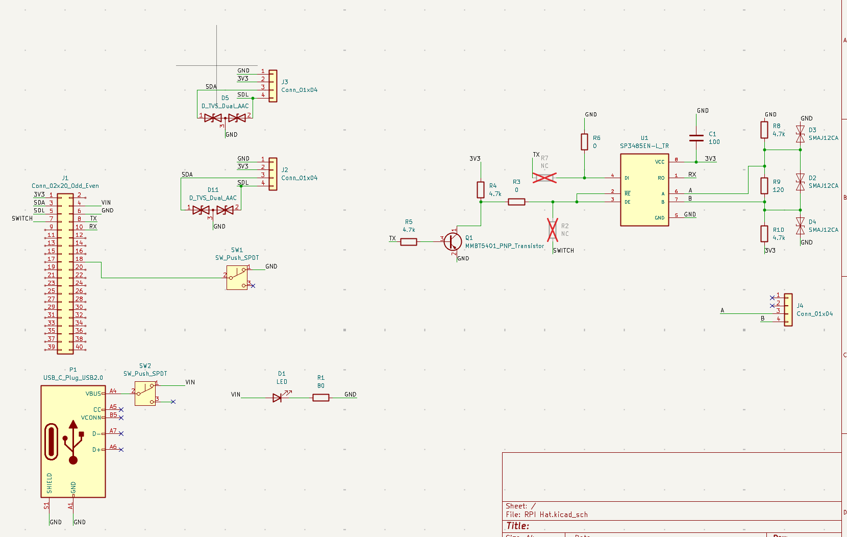
Schematic
Design Details
RS485 Transceiver
The board uses an SP3485EN-L_TR RS485 transceiver for communication with the VEX V5 brain:
- DI/RO: Data in/out connected to Pi's TX/RX pins
- RE/DE: Direction control via PNP transistor (Q1 - MMBT5401)
- A/B: Differential pair output to J4 connector
- ESD Protection: SMAJ12CA TVS diodes (D2, D3, D4) clamp transients on the RS485 lines
The direction switching uses a transistor rather than direct GPIO to ensure proper timing and drive strength.
Dual I2C Ports
Two 4-pin I2C connectors (J2, J3) with identical pinout:
| Pin | Signal |
|---|---|
| 1 | GND |
| 2 | 3V3 |
| 3 | SDA |
| 4 | SCL |
Each port has TVS dual diodes (D5, D11 - D_TVS_Dual_AAC) for ESD protection on the data lines. Both ports share the same I2C bus from the Pi.
Power Circuit
- USB-C Input (P1): VBUS provides 5V power
- Power Switch (SW2): SPDT switch between VBUS and VIN rail
- Power LED (D1): Indicates when board is powered, with R1 current limiting resistor
- 3V3 Rail: Sourced from Pi's 3.3V regulator via GPIO header
GPIO Switch
SW1 is a general-purpose SPDT switch directly connected to a Pi GPIO pin. Used for robot configuration (e.g., selecting Blue vs Gold robot mode).
Component Selection
| Component | Part | Rationale |
|---|---|---|
| RS485 Transceiver | SP3485EN-L_TR | 3.3V compatible, low power, half-duplex |
| Direction Transistor | MMBT5401 | PNP for active-low RE control |
| RS485 TVS | SMAJ12CA | 12V standoff, handles ESD and voltage spikes |
| I2C TVS | D_TVS_Dual_AAC | Dual-line protection in single package |
Connectors
The main motivation for this board was replacing unreliable header connections with proper locking connectors:
| Connector | Type | Purpose |
|---|---|---|
| J1 | 2x20 Header | Pi GPIO interface |
| J2, J3 | 4-pin JST | I2C sensors (Pinpoint) |
| J4 | 4-pin JST | RS485 to VEX brain |
| P1 | USB-C | Power input |
Fabrication
- PCB Fab: JLCPCB (2-layer board)
- Assembly: Hand-soldered SMD components
- Status: Designed and ordered, but not tested before Worlds due to shipping delays
Tech Stack
| Area | Tools |
|---|---|
| Schematic & Layout | KiCad |
| 3D Modeling | KiCad 3D Viewer |
| Fabrication | JLCPCB |
| Documentation | TBD |
More in KUdos Custom Electronics Stack
KUdos Robot Manager
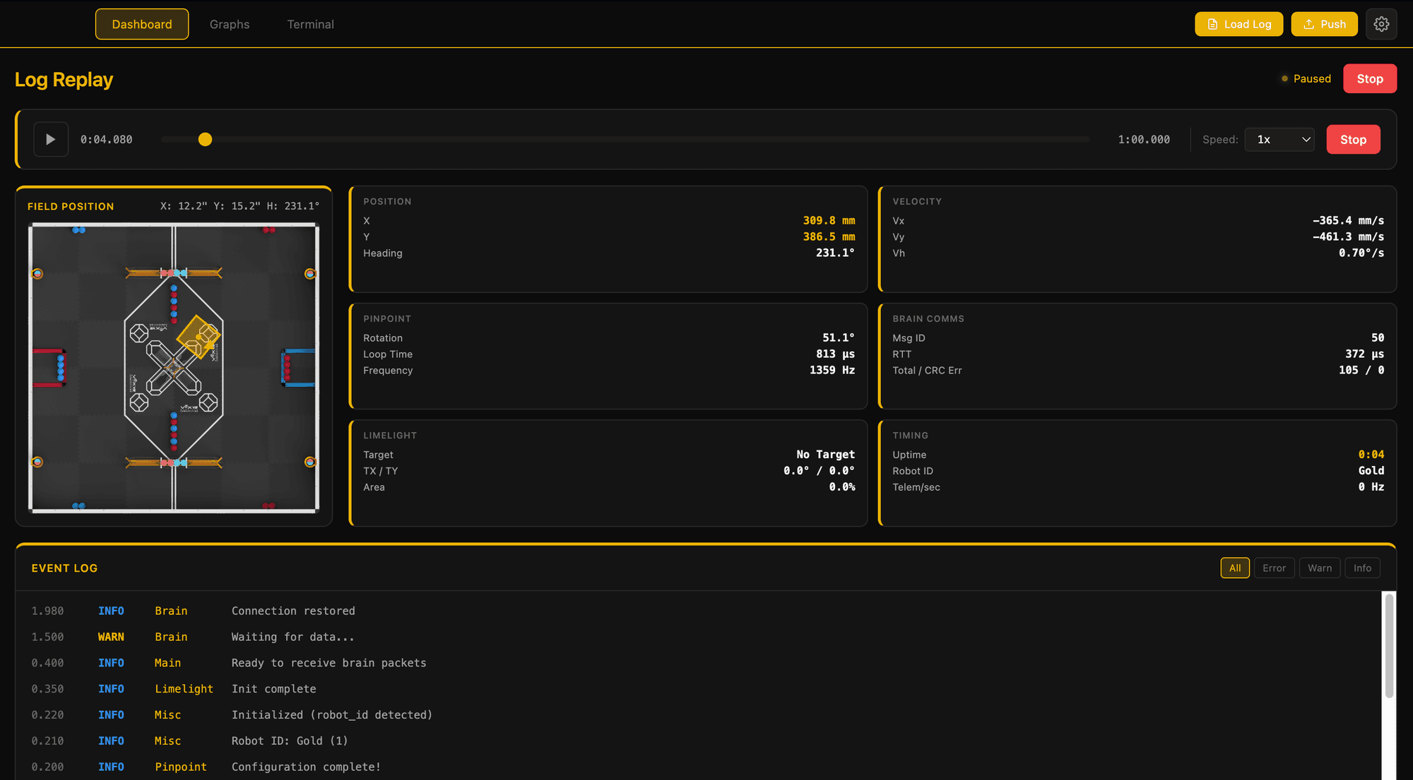
An Electron desktop app for managing VEX-U robots with SSH deployment, Limelight tunneling, and live terminal access.
KUdos Coprocessor Firmware
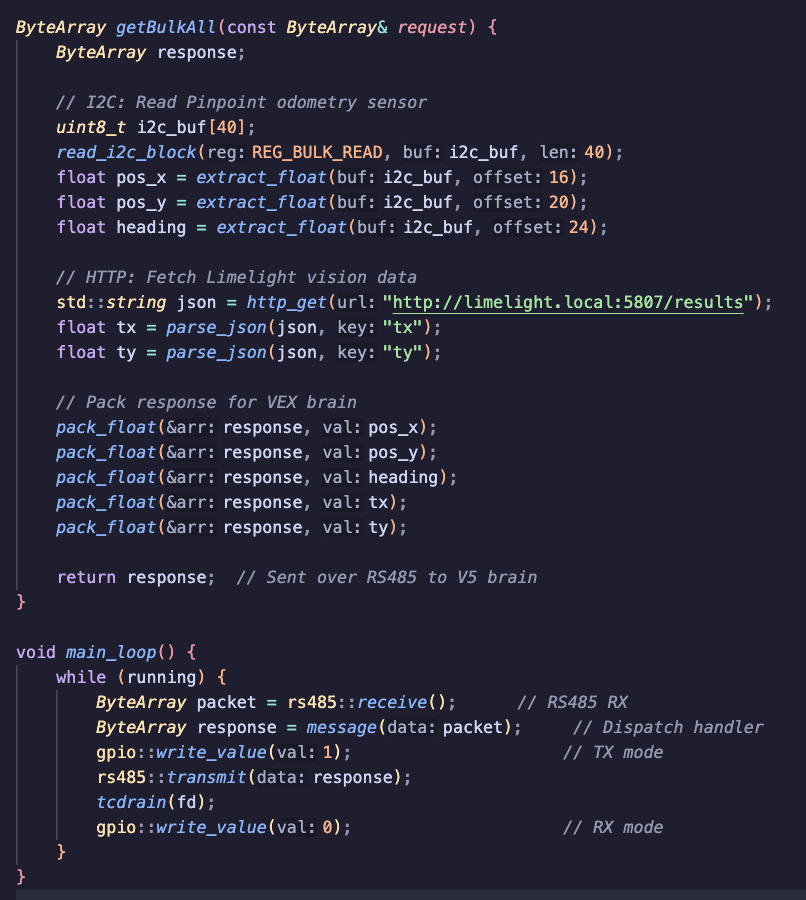
The firmware running on the Raspberry Pi coprocessor for sensor fusion, vision processing, and communication with the VEX brain.
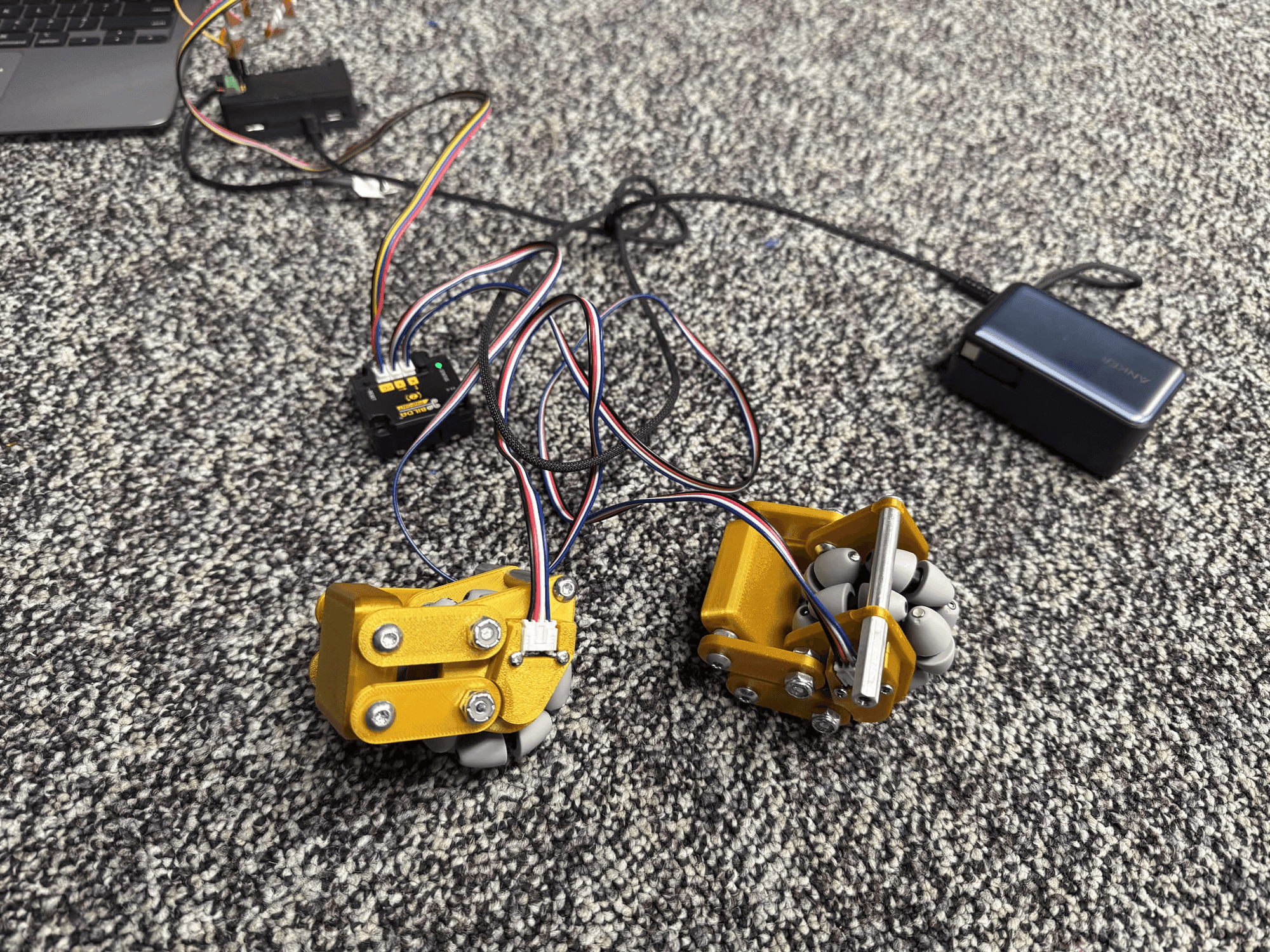
KUdos Electronics Bringup
The real-world integration and testing of the custom electronics stack on competition robots.
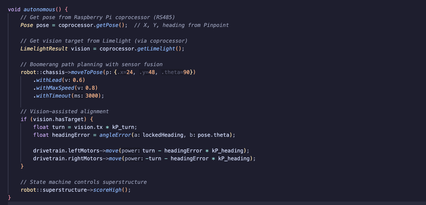
KUdos 2025-2026 Robot Code
The competition robot code for KUdos VEX-U, implementing autonomous routines and driver control with custom chassis systems.
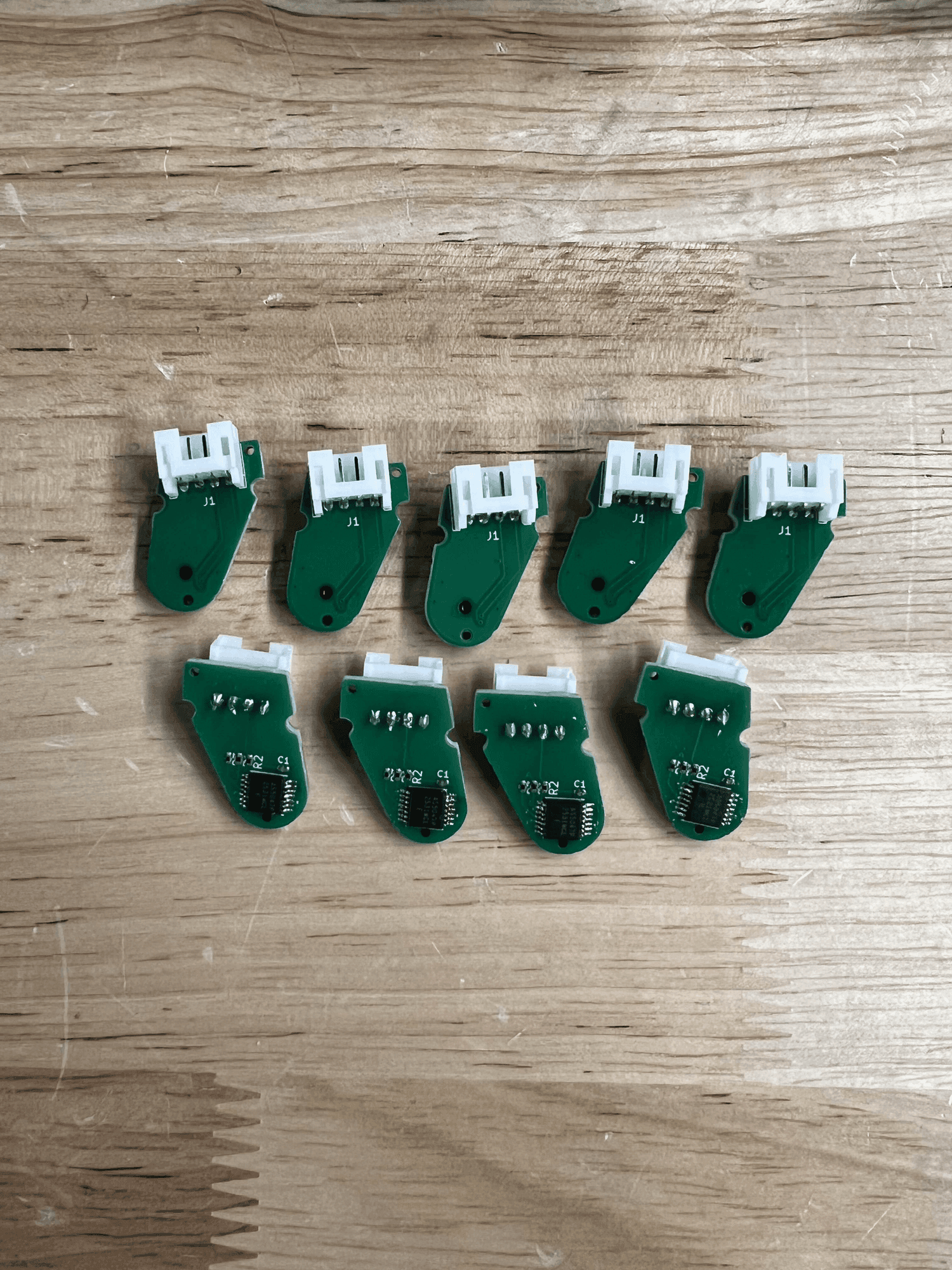
KUdos Magnetic Encoder
A custom quadrature magnetic encoder PCB using the AS5047P for high-resolution odometry on VEX-U robots.