Part of KUdos Custom Electronics Stack
KUdos Coprocessor Firmware
The firmware running on the Raspberry Pi coprocessor for sensor fusion, vision processing, and communication with the VEX brain.
Project Overview
The KUdos coprocessor firmware runs on a Raspberry Pi Zero 2W mounted on the custom expansion HAT. It handles sensor fusion, Limelight vision data processing, and communication with the VEX V5 brain over RS485.
This firmware is the bridge between the high-level processing capabilities of a Linux system and the real-time control of the VEX robotics platform.
Role: Firmware developer
Tech Stack: C++, Linux, systemd, RS485
Responsibilities
- Sensor Fusion: Aggregate data from I2C sensors
- Vision Processing: Parse Limelight NetworkTables data
- Communication: RS485 protocol to VEX V5 brain
- Service Management: Runs as a systemd service
Architecture
The firmware runs a main loop that handles communication with the VEX V5 brain while background threads manage sensor polling and status reporting.
┌─────────────────────────────────────────────────────┐
│               Raspberry Pi Zero 2W                  │
├─────────────────────────────────────────────────────┤
│  Main Thread          │  Background Threads         │
│  ─────────────────    │  ─────────────────────      │
│  • Brain comms loop   │  • Status printing (2s)     │
│  • Message dispatch   │  • Limelight init           │
│  • Response sending   │  • Hotspot switch monitor   │
└──────────┬────────────┴─────────────┬───────────────┘
           │                          │
    ┌──────▼──────┐           ┌───────▼───────┐
    │   RS485     │           │     I2C       │
    │  UART + GPIO│           │   /dev/i2c-1  │
    └──────┬──────┘           └───────┬───────┘
           │                          │
    ┌──────▼──────┐           ┌───────▼───────┐
    │  VEX V5     │           │   Pinpoint    │
    │   Brain     │           │   Odometry    │
    └─────────────┘           └───────────────┘
Message Protocol
Communication with the VEX brain uses a custom RS485 protocol with:
- Delimiter:
0xAA 0x55packet start marker - Length: 16-bit big-endian payload length
- CRC16: Checksum for data integrity
- Byte stuffing: Escapes delimiters and escape characters in payload
// Packet format:
// [DELIMITER_1 DELIMITER_2] [16-bit length] [CRC16] [stuffed payload]

constexpr uint8_t DELIMITER_1 = 0xAA;
constexpr uint8_t DELIMITER_2 = 0x55;
constexpr uint8_t ESCAPE = 0xBB;
GPIO Direction Control
RS485 is half-duplex, so a GPIO pin controls the transceiver direction:
gpio::write_value(1);  // TX mode
transmit(header);
transmit(payload);
tcdrain(fd);           // Wait for UART buffer to flush
gpio::write_value(0);  // RX mode
Implementation Details
Message Registry
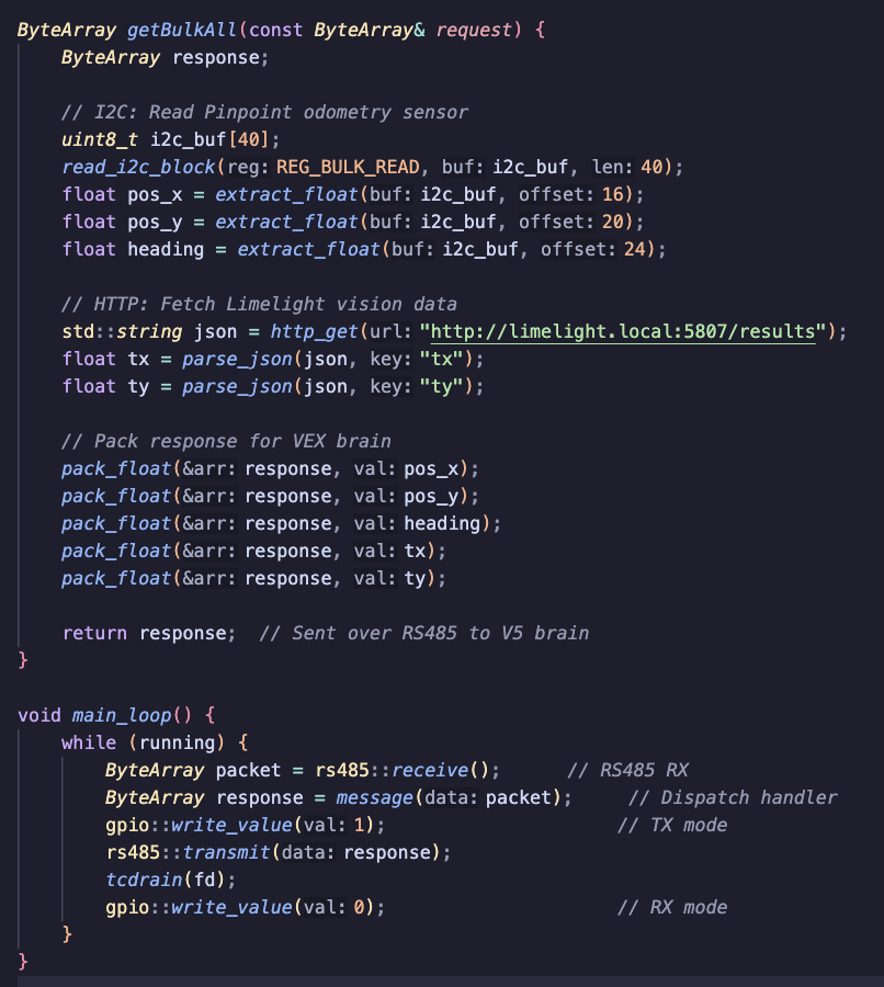
The firmware exposes 52 message handlers, each mapped to an ID. When a packet arrives, the first byte is the message ID, and the firmware dispatches to the corresponding handler:
ByteArray message(const ByteArray& data) {
    static std::vector<MsgF> registry = {
        getCoprocessorVersion,    // 0
        pinpoint::getStatus,      // 1
        pinpoint::getVersion,     // 2
        // ... pinpoint functions 1-34
        // ... misc functions 35-39
        // ... limelight functions 40-49
        getBulkAll,               // 50 - Combined sensor data
        pinpoint::resetPosAndIMUBlocking  // 51
    };

    const uint8_t id = data.at(0);
    const ByteArray raw = registry.at(id)(data);
    // Prepend message ID to response
    ByteArray rtn = {id};
    rtn.insert(rtn.end(), raw.begin(), raw.end());
    return rtn;
}
Pinpoint Odometry Sensor
The goBILDA Pinpoint odometry computer is read via I2C. The firmware reads bulk data (40 bytes) containing position, velocity, heading, and encoder counts:
// Bulk data format (little-endian):
// device_status (4) + loop_time (4) + encoder_x (4) + encoder_y (4)
// + pos_x (4) + pos_y (4) + heading (4) + vel_x (4) + vel_y (4) + vel_h (4)

uint8_t buffer[40];
read_i2c_block(REG_BULK_READ, buffer, 40);
The firmware also tracks unbounded rotation (across ±180° boundaries) for autonomous routines that need to know total angular displacement.
Limelight Vision Integration
The Limelight camera is accessed via HTTP requests to its REST API:
// Get vision results as JSON
std::string json = http_get("http://limelight.local:5807/results");

// Parse and return: validity, pipeline, tx, ty, ta
Json::Value root;
Json::Reader reader;
reader.parse(json, root);

float tx = root.get("tx", 0.0f).asFloat();
float ty = root.get("ty", 0.0f).asFloat();
float ta = root.get("ta", 0.0f).asFloat();
Limelight initialization runs in a background thread to avoid blocking brain communication during startup.
Bulk Data Optimization
For efficiency, the robot code can request all sensor data in a single message (ID 50) rather than multiple round-trips:
auto getBulkAll = [](const ByteArray&) -> ByteArray {
    ByteArray result;

    // Get Pinpoint data (48 bytes)
    auto pinpoint_data = pinpoint::getBulkData({});
    result.insert(result.end(), pinpoint_data.begin(), pinpoint_data.end());

    // Get Limelight data (14 bytes per camera)
    auto ll_data = limelight::getResultsByIndex({0});
    result.push_back(ll_count);
    result.insert(result.end(), ll_data.begin(), ll_data.end());

    return result;
};
Serial Port Configuration
The firmware opens the serial port directly using Linux syscalls, bypassing higher-level libraries for maximum control:
fd = ::open(BRAIN_SERIAL_PORT, O_RDWR | O_NOCTTY | O_NDELAY);

struct termios options;
tcgetattr(fd, &options);

// 8N1, no flow control
options.c_cflag &= ~PARENB;      // No parity
options.c_cflag &= ~CSTOPB;      // 1 stop bit
options.c_cflag &= ~CSIZE;
options.c_cflag |= CS8;          // 8 data bits
options.c_cflag &= ~CRTSCTS;     // No hardware flow control
options.c_cflag |= CLOCAL | CREAD;

// Raw input/output (no line buffering, no echo)
options.c_lflag &= ~(ICANON | ECHO | ECHOE | ISIG);
options.c_iflag &= ~(IXON | IXOFF | IXANY);

tcsetattr(fd, TCSANOW, &options);
The baud rate is configurable (default 115200) and the port is set to non-blocking mode with no read timeout, allowing the main loop to poll efficiently.
Pinpoint Configuration
On startup, the firmware configures the Pinpoint odometry sensor with robot-specific parameters:
void init() {
    fd = open("/dev/i2c-1", O_RDWR);
    ioctl(fd, I2C_SLAVE, PINPOINT_I2C_REG);

    // Set encoder resolution (ticks per mm)
    write_float_register(REG_TICKS_PER_MM, PINPOINT_TICKS_PER_MM);

    // Set tracking wheel offsets from robot center
    write_float_register(REG_X_POD_OFFSET, PINPOINT_X_POD_OFFSET);
    write_float_register(REG_Y_POD_OFFSET, PINPOINT_Y_POD_OFFSET);

    // Set encoder directions (forward/reversed)
    write_uint32_register(REG_DEVICE_CONTROL, SET_X_ENCODER_REVERSED);
    write_uint32_register(REG_DEVICE_CONTROL, SET_Y_ENCODER_FORWARD);

    // Reset position and IMU on startup
    write_uint32_register(REG_DEVICE_CONTROL, RESET_IMU_AND_POSITION);
}
These values are defined in a configuration header and can be adjusted for different robot geometries.
Unbounded Rotation Tracking
The Pinpoint sensor reports heading in the range ±π radians. For autonomous routines that involve multiple rotations (like skills runs), the firmware tracks total rotation across these boundaries:
double update_rotation_tracking(double current_heading_rad) {
    double current_deg = current_heading_rad * (180.0 / M_PI);

    // Calculate shortest angular difference
    double delta = current_deg - last_normalized_heading_deg;

    // Handle wraparound at ±180°
    if (delta > 180.0) {
        delta -= 360.0;  // Crossed from +180 to -180
    } else if (delta < -180.0) {
        delta += 360.0;  // Crossed from -180 to +180
    }

    total_rotation_deg += delta;
    last_normalized_heading_deg = current_deg;

    return total_rotation_deg;
}
This allows the robot code to know, for example, that the robot has rotated 720° total rather than just seeing repeated 0° readings.
Data Validation
I2C communication can produce garbage data when the bus is noisy or the sensor is busy. The firmware validates all readings before returning them:
static bool is_valid_float(float val) {
    return std::isfinite(val) && std::fabs(val) < 1e9f;
}

// In getBulkData:
if (!is_valid_float(pos_x) || !is_valid_float(pos_y) || !is_valid_float(heading_raw)) {
    // Suppress warning if within 300ms of zeroing (expected transient)
    auto since_zero = std::chrono::steady_clock::now() - last_zero_time;
    if (std::chrono::duration_cast<std::chrono::milliseconds>(since_zero).count() > 300) {
        printf("[Pinpoint] Invalid data detected - I2C error?\n");
    }
    return {1}; // Return error instead of garbage
}
This prevents corrupted data from causing erratic robot behavior.
Blocking IMU Reset
For reliable autonomous startup, the robot code can request a blocking reset that waits for the IMU to calibrate:
message::MsgF resetPosAndIMUBlocking = [](const ByteArray&) -> ByteArray {
    // Send reset command
    write_uint32_register(REG_DEVICE_CONTROL, RESET_IMU_AND_POSITION);

    // Poll device status until READY and not CALIBRATING
    constexpr int MAX_POLLS = 200;  // 2 second timeout
    for (int i = 0; i < MAX_POLLS; i++) {
        uint8_t buffer[4];
        read_i2c_block(REG_BULK_READ, buffer, 4);

        uint32_t status;
        memcpy(&status, buffer, 4);

        bool is_ready = (status & STATUS_READY) != 0;
        bool is_calibrating = (status & STATUS_CALIBRATING) != 0;

        if (is_ready && !is_calibrating) {
            return {0}; // Success
        }

        std::this_thread::sleep_for(std::chrono::milliseconds(10));
    }

    return {1}; // Timeout
};
This ensures the robot doesn't start moving before the IMU is stable, which would cause heading drift.
CRC16 Implementation
The protocol uses CRC-16/CCITT-FALSE for error detection:
uint16_t crc16(const std::vector<uint8_t>& data) {
    uint16_t crc = 0xFFFF;
    for (uint8_t byte : data) {
        crc ^= (static_cast<uint16_t>(byte) << 8);
        for (int i = 0; i < 8; i++) {
            if (crc & 0x8000) {
                crc = (crc << 1) ^ 0x1021;
            } else {
                crc <<= 1;
            }
        }
    }
    return crc;
}
If the received CRC doesn't match the computed CRC, the packet is rejected and an error is returned.
Why a Coprocessor?
VEX V5 has limitations that motivated adding a Raspberry Pi coprocessor:
- Limited I2C support: The V5 brain has restricted I2C capabilities; the Pi provides full I2C bus access
- No native Limelight integration: The Pi can fetch JSON from the Limelight's REST API
- Processing power: The Pi can run sensor fusion algorithms that would burden the V5 brain
- Debugging: Linux provides logging, SSH access, and easier development iteration
The trade-off is added complexity in hardware and communication, but for VEX-U (university-level) competition, the enhanced capabilities are worth it.
Tech Stack
| Area | Tools |
|---|---|
| Language | C++ |
| Platform | Raspberry Pi OS |
| Build | Make |
| Service | systemd |
More in KUdos Custom Electronics Stack
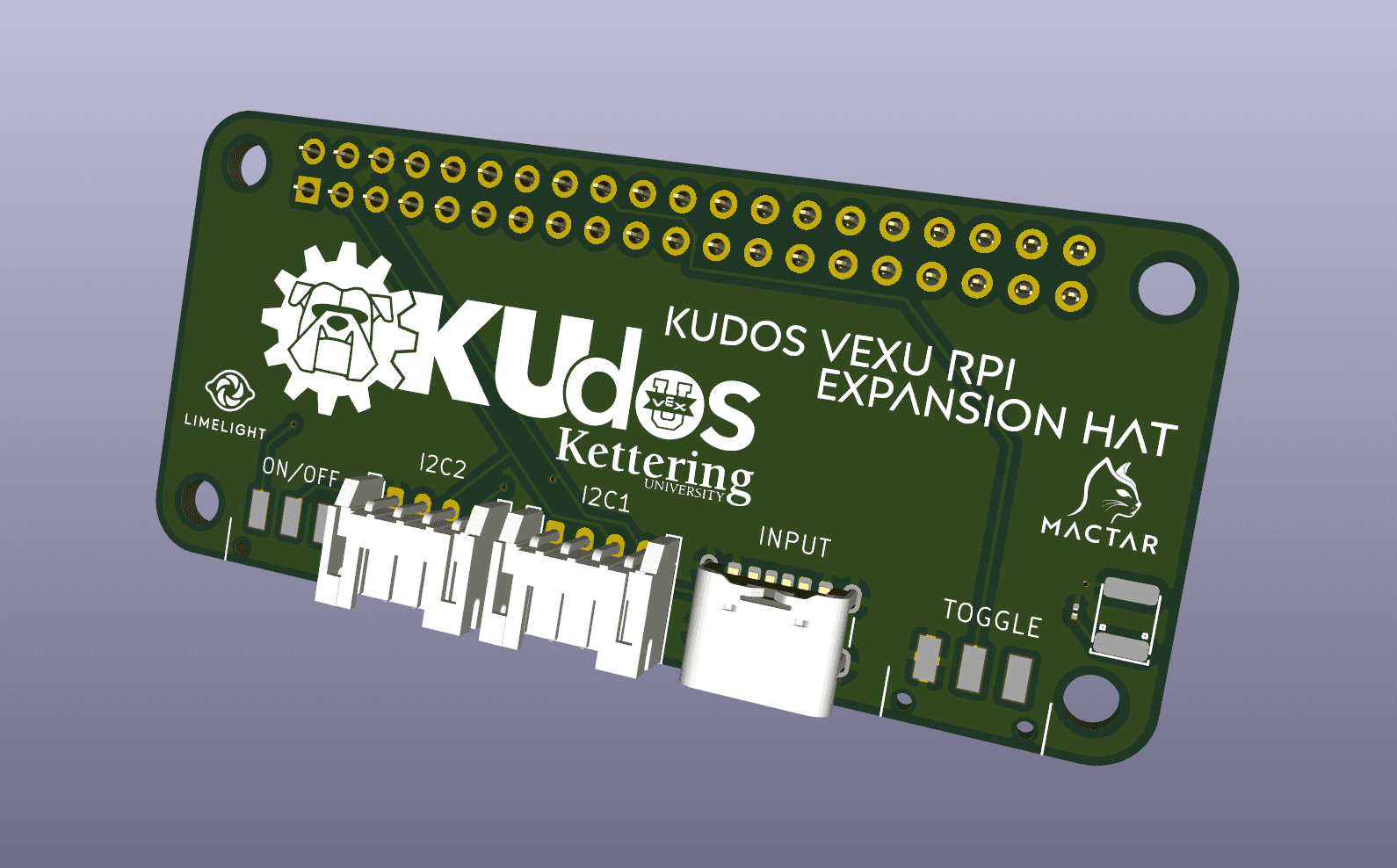
KUdos RPi Expansion HAT
A custom PCB for Raspberry Pi Zero 2W providing I2C interfacing and native RS485 communication for VEX-U robotics.
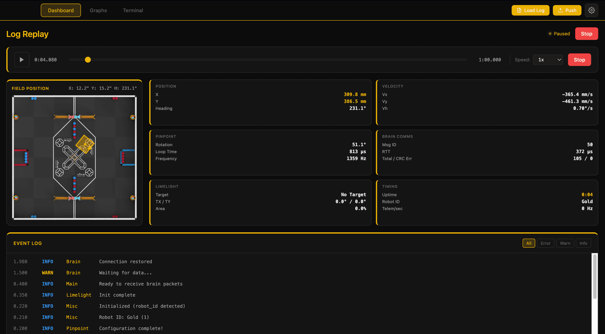
KUdos Robot Manager
An Electron desktop app for managing VEX-U robots with SSH deployment, Limelight tunneling, and live terminal access.
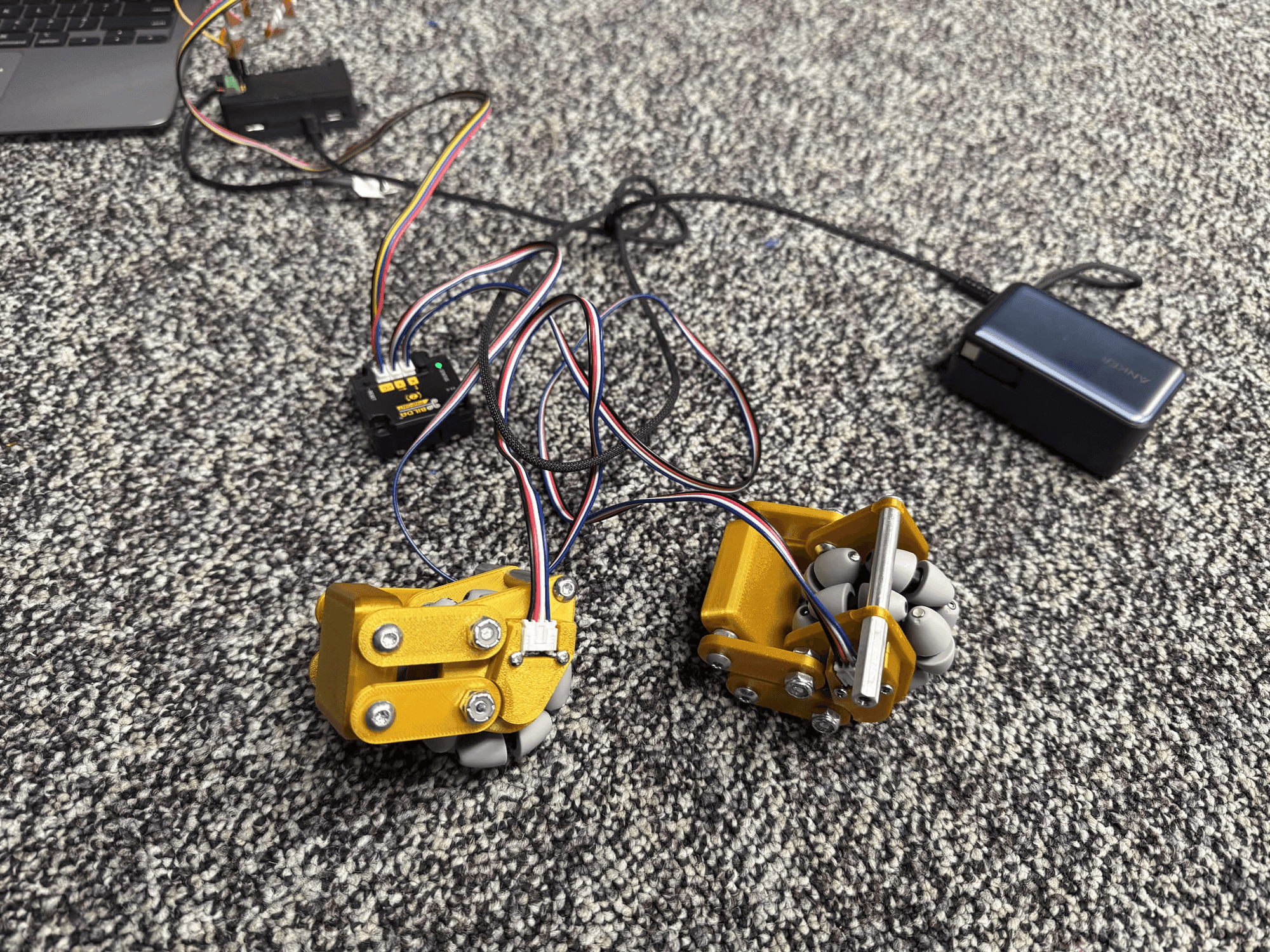
KUdos Electronics Bringup
The real-world integration and testing of the custom electronics stack on competition robots.
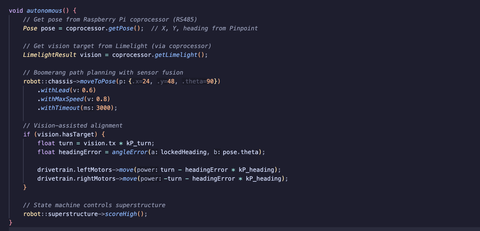
KUdos 2025-2026 Robot Code
The competition robot code for KUdos VEX-U, implementing autonomous routines and driver control with custom chassis systems.
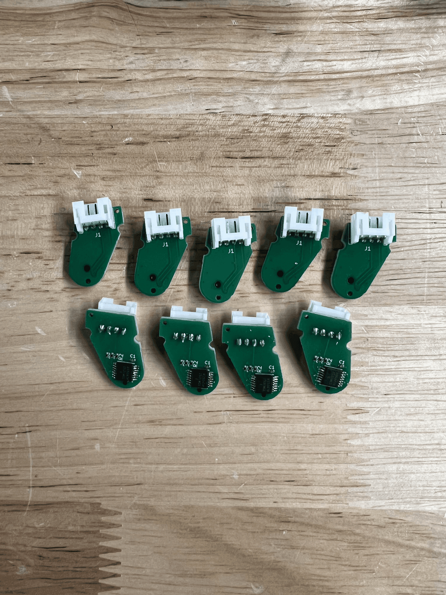
KUdos Magnetic Encoder
A custom quadrature magnetic encoder PCB using the AS5047P for high-resolution odometry on VEX-U robots.