Limelight Monorail — Power Distribution Board
A compact power distribution board designed for daisy chaining, featuring fused outputs and optimized connector sizing for robotics applications.
Project Overview
Monorail is a power distribution board designed at Limelight for robotics applications. The board enables clean daisy-chained power distribution with individually fused outputs. The current version is optimized for 18AWG and smaller wire, reducing tradeoffs and improving ergonomics for low-current applications.
Role: Electronics Designer
Company: Limelight
Tools: PCB Design Software
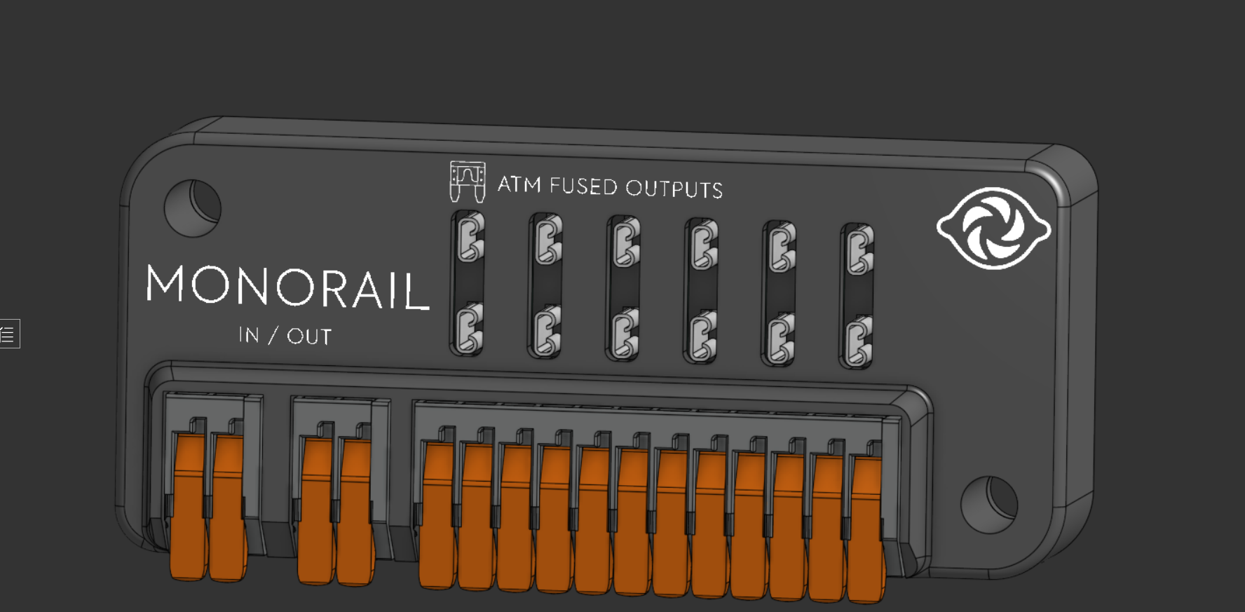
Design Evolution
Rev 1 — Initial Prototype
The first revision was a basic power distribution board with no fused outputs. This design was vulnerable to overcurrent conditions that could damage the board.
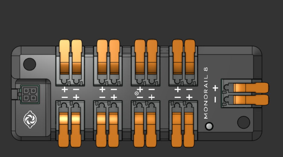
Issues:
- No overcurrent protection
- Single point of failure risk
- Limited safety for connected devices
Rev 2 — Fused Outputs & Daisy Chaining
Added ATM fuse holders for each output channel, providing individual overcurrent protection. Also introduced daisy chain capability allowing multiple boards to be connected in series.
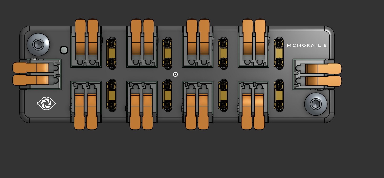
Improvements:
- ATM fused outputs for overcurrent protection
- Daisy chain connectors for expandability
- Individual channel protection
Rev 3 — Connector Optimization
Revised the connector sizing to better accommodate the target wire gauges. The previous connectors were awkwardly sized—too small for 10AWG but too large for smaller gauge wires. Committed to optimizing for 18AWG and smaller, eliminating the tradeoffs.
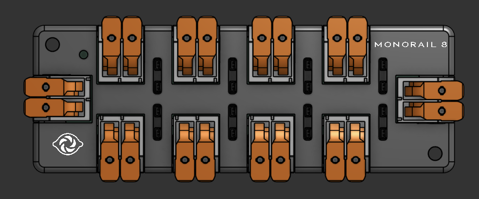
Improvements:
- Right-sized connectors for 18AWG and smaller
- Improved ergonomics for wire insertion
- No more sizing compromises
Final — Corner Mounting
The final revision addressed mounting constraints by adding corner mounting provisions. This allows the board to be mounted in tight spaces where traditional rectangular mounting isn't feasible.
Key Features:
- Corner mounting holes for flexible installation
- Committed PCB cornering design
- Optimized for real-world robot packaging
Revision Comparison
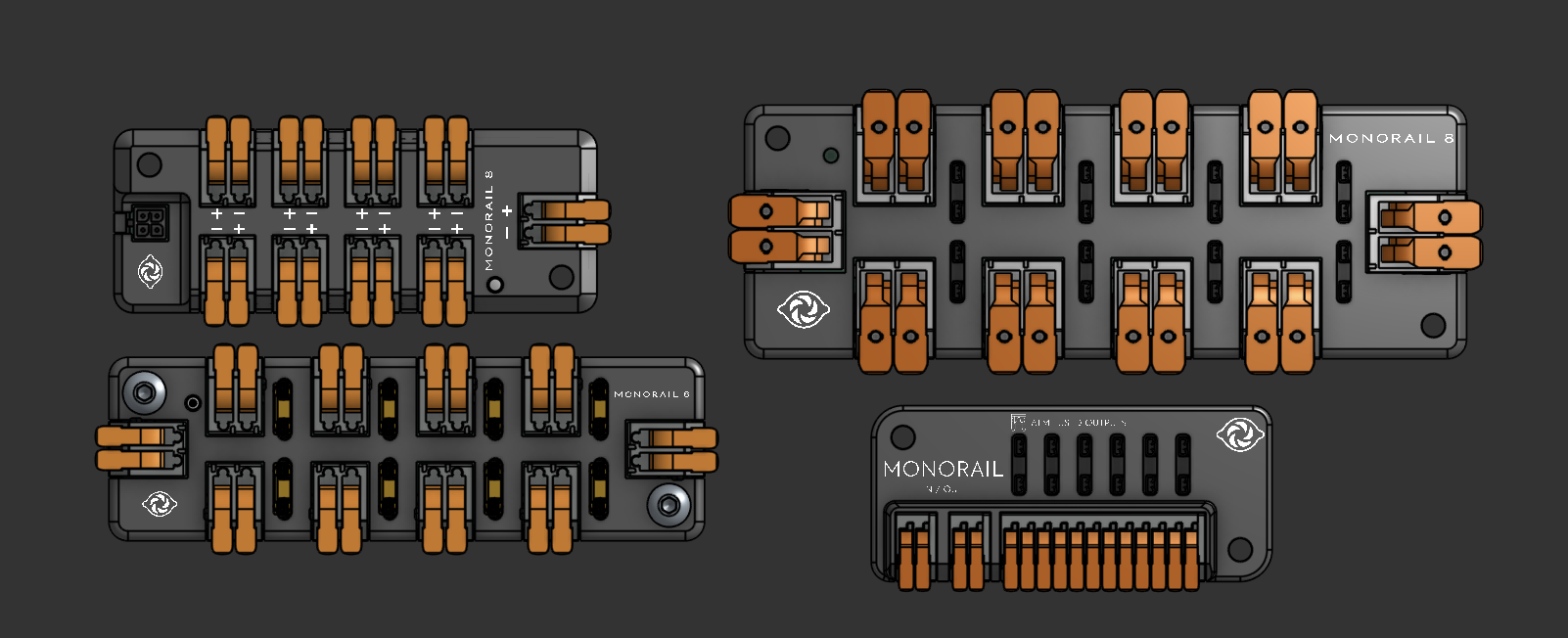
Side-by-side comparison showing the evolution from the unfused prototype through connector optimization to the final corner-mounted design.
Schematic
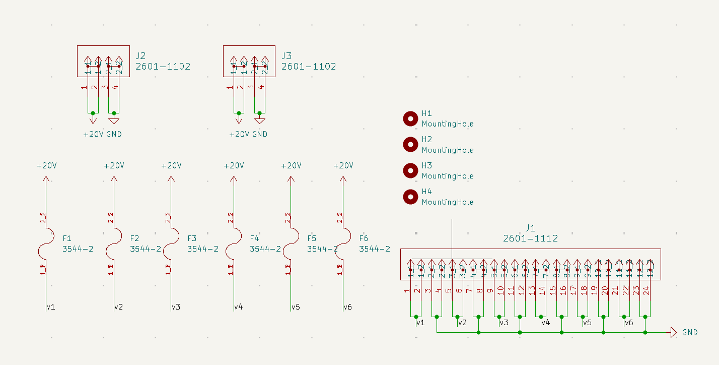
The schematic shows:
- J2/J3 (2601-1102): Daisy chain input/output connectors (+20V and GND)
- F1-F6 (3544-2): ATM fuse holders for individual channel protection
- J1 (2601-1112): 24-position output connector with fused V1-V6 outputs and GND
- H1-H4: Corner mounting holes
Features
| Feature | Specification |
|---|---|
| Outputs | 8 fused channels |
| Fuse Type | ATM (automotive mini) |
| Daisy Chain | Yes — IN/OUT connectors |
| Wire Gauge | 18AWG and smaller |
| Mounting | Corner-optimized |
First Power On Test
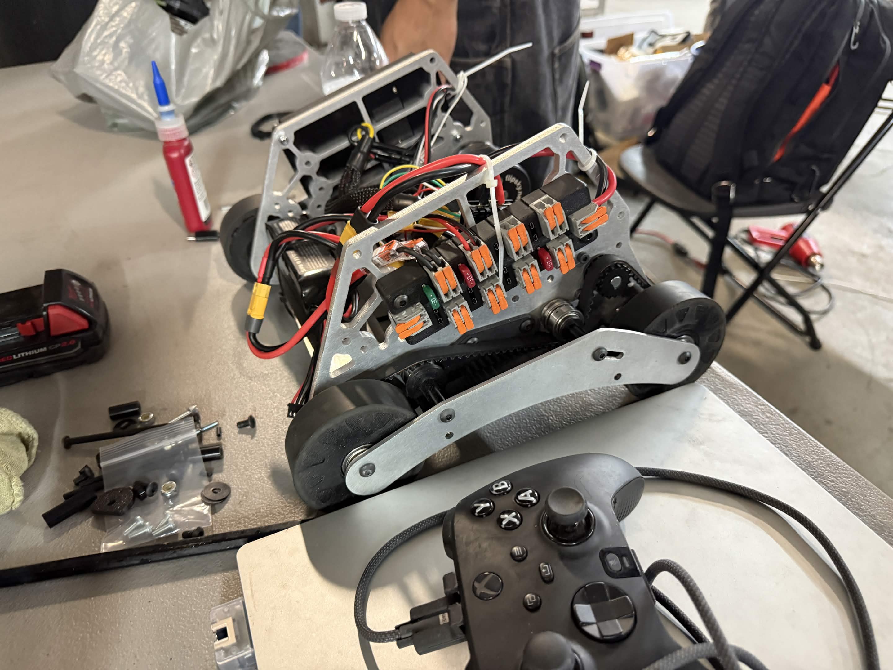
First power on test performed at the Rival Doomsday Hackathon.
Tech Stack
| Area | Tools |
|---|---|
| PCB Design | KiCad / Altium |
| 3D Modeling | Onshape |