FRC Team 987 Robot Design
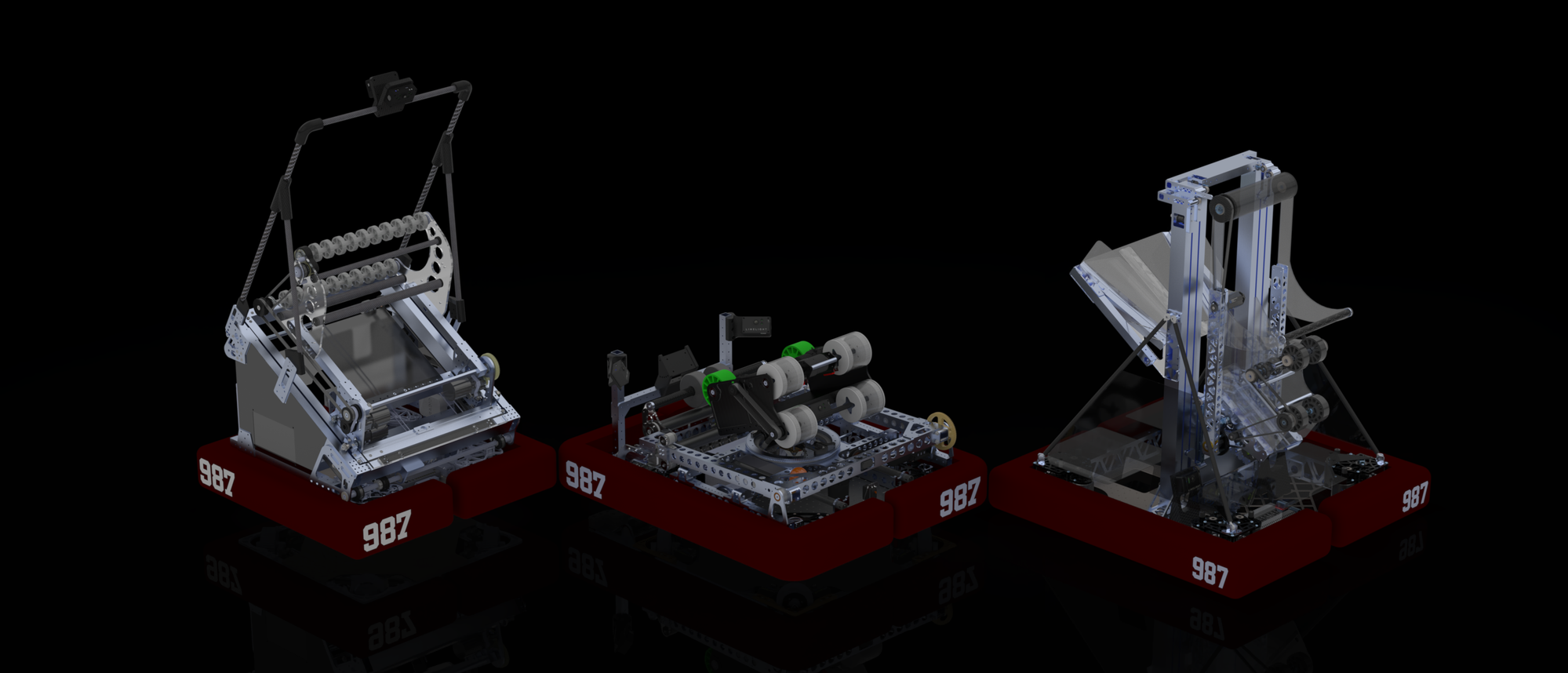
Three competition robots designed as CAD Lead for FRC Team 987, including a Championship Division Winner. Featured a custom multibody workflow in SolidWorks.
Project Overview
As CAD Lead for FRC Team 987, I led the mechanical design of competition robots for the 2024-2025 season and contributed significantly to the 2023-2024 season. These three robots earned multiple regional wins and a Championship Division title at the World Championship.
Role: CAD Lead (2024-2025), Design Contributor (2023-2024)
Team: FRC Team 987
Tools: SolidWorks
Competition Results
2025 Season — Reefscape
| Event | Result |
|---|---|
| World Championship | Competed (Archimedes Division) |
| Las Vegas Regional | Regional Winners, Autonomous Award |
| Utah Regional | Regional Winners, Autonomous Award |
2024 Season — Crescendo
| Event | Result |
|---|---|
| World Championship | Galileo Division Winner → Top 8 Worldwide |
| Las Vegas Regional | Regional Winners, Excellence in Engineering Award |
| Silicon Valley Regional | Autonomous Award |
Winning a Championship Division at Worlds places a team in the top 8 globally.
2023 Season — Charged Up
| Event | Result |
|---|---|
| Beach Blitz | Competed |
The Robots
2025 Robot — "Card Shark" (Reefscape)
Key Mechanisms:
- 3-Stage Elevator — In-tube belt system with 2x Kraken X60 motors (2.6:1 ratio), constant force springs for retraction
- Coral Shooter — Dual-orientation design (parallel for L2-L4, perpendicular for L1), CANRange sensor for positioning
- Algae Arm — 130:1 pivot gearbox, compliant plastic end effector, rubber mastic tape roller for grip
- Funnel — 35° loading angle collinear with station, trap door floor for cage climbing
- Drivetrain — WCP Swerve X2i modules, 29" x 29" frame with steel bellypan
- Vision — Two Limelight 4 cameras with Hailo Accelerator for pose estimation
2024 Robot — "The Dealer's Revenge" (Crescendo)
Key Mechanisms:
- 360° Turret + Tilt — Gas-shock stabilized tilt, NEO-550 powered winch, custom HTD pulley on COTS bearing
- Vertical Shooter — NEO Vortex motors, custom 4" polycarbonate wheels, 0.5" compression, IR sensors for note detection
- Under-Bumper Intake — Protected design with 2" compliant wheels, 1" counter-roller for ground pickup
- Amp/Trap/Handoff Arm — Dual telescopes with constant force springs, servo-released extension
- Climber — Winch-driven rip-off hooks integrated into arm, stabilizing forks with carbon fiber extension
- Drivetrain — Custom swerve (MK4i-based) with steel plates, 32.5" x 26" frame, up to 23.6 ft/s
- Vision — Three Limelights (2x 3G for pose, 1x 3 for note tracking with Google Coral)
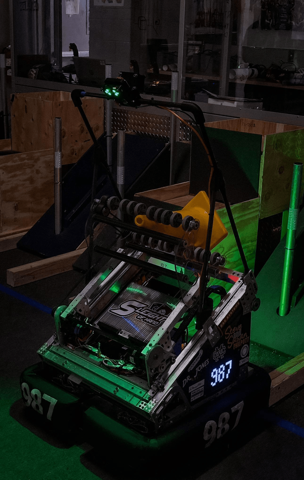
2023 Robot — "Sleight of Hand" (Charged Up Offseason)
Key Mechanisms:
- Drivetrain — Custom SDS MK4i swerve with 20t pinion (vs stock 14t), resulting in 4.29:1 reduction and 24.5 ft/s top speed (vs 17.2 ft/s stock). Robot built lightweight to maximize acceleration with higher top speed
- Cube Intake — 2" compliant wheels on carbon fiber cross beams (cube-specialized robot)
- Elevator — 3:1 cascade rigged elevator with belt clamp driven first stage
- Arm — 1" x 1" x 1/16" aluminum tube arm with 2-stage planetary into single-stage gear reduction
- Limelight Mast — Carbon fiber structure with epoxy and 3D-printed gussets, housing two Limelight 3s on clamped mounts for gamepiece detection and driver assist
- Vision — Three Limelight 3 cameras total (2 on mast, 1 rear-facing for AprilTag alignment)
Multibody Workflow Innovation
In 2025, I developed a multibody modeling workflow in SolidWorks that mimicked Onshape's approach to collaborative design. The key innovation was modeling parts in context of each other within a single multibody part file.
The Problem
Traditional SolidWorks workflow:
- Single assembly file = one designer at a time
- Parts designed in isolation, then assembled
- Merge conflicts when multiple people edit
- Long rebuild times as assembly grows
- Difficult to parallelize work across subsystems
The Solution
Masterpart + Mastersketch approach:
-
Mastersketch — A single sketch defines the robot's key dimensions and geometry. All subsystem masterparts reference this sketch, so updating one dimension propagates changes across the entire robot.
-
Subsystem Masterparts — Each subsystem has its own masterpart file where all parts are modeled as bodies. Parts are designed in context of each other within that subsystem.
-
Export — Individual parts are exported from each masterpart for manufacturing drawings and the final assembly.
| File | Contents |
|---|---|
| Mastersketch | Robot dimensions, all masterparts reference this |
| 210 Elevator | Elevator bodies → exported parts |
| 220 Coral | Coral shooter bodies → exported parts |
| 230 Algae | Algae arm bodies → exported parts |
| 240 Funnel | Funnel bodies → exported parts |
| 250 Climb | Climber bodies → exported parts |
Parametric Design
The key advantage is parametricity — change a sketch dimension and the entire robot updates:
- Update frame width in mastersketch → all mounting holes, plates, and clearances adjust
- Parts designed in context automatically fit together
- Interference is visible immediately during design, not after assembly
- Subsystems can be worked on in parallel by different designers
Impact
| Metric | Before | After |
|---|---|---|
| Designers working simultaneously | 2-3 | 4-5 |
| Assembly rebuild time | ~5 min | ~30 sec |
| Design iteration speed | Medium | Fast |
What I Learned
- Design for manufacturing: Every part needs to be machinable with available tools
- Iteration speed matters: The faster you can test ideas in CAD, the better the final robot
- Collaboration at scale: Leading a CAD team requires good file organization and workflows
- Mechanical intuition: After 3 robots, you develop a sense for what will work before building it
- Process innovation: Sometimes improving how you work is as valuable as the work itself
Tech Stack
| Area | Tools |
|---|---|
| CAD | SolidWorks |
| Rendering | SolidWorks Visualize |
| Collaboration | Multibody workflow, PDM |
| Manufacturing | CNC, 3D Printing, Sheet Metal |